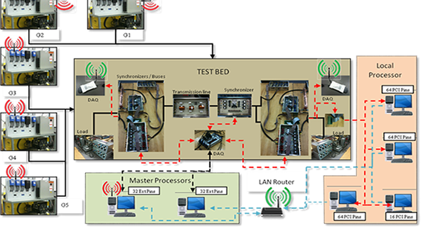
The self-managing and reliable smart grid is seen as the future of protection and control systems. By using generation stations, transmission lines, synchronizers, DAQs, Loads, and also using the new wireless communication layers, test bed will have the following structure as the schematic:

Schematic Diagram of Power Systems Test-Bed.
Single line diagram for this test-bed uses 208 V, 60 Hz, AC generator which includes AVR and Drive model for voltage and frequency support. All buses have 208 V line to line voltages and at the end buses we have diferrent loads as passive load and dynamic motor loads. All lines have different line parameters which we measured from the actual available models.

Single Line Diagram of Power Systems Test-Bed.
All proposed system will be implemented in test-bed power system which is currently is underdeveloped in Energy System Research Lab in Florida International University. This setup includes at least four generation as main power sources which are modeling conventional power plants. This is the present setup in our laboratory.

Power Systems Test-Bed Setup.

Power Systems Test-Bed Setup.

Power Systems Test-Bed Setup
For this stage a two generator connections to power system including impedance and motor loads was developed. It is possible to measure all currents and voltages of buses by using national instrument DAQs. The LabVIEW software is used for gathering all data on its environment and this software has the capability to control power system by switching operations and generation control set points which are developed until now. The control and protection strategies will be implemented by using this software as well as overall real time monitoring of smart power system. Overall Control and Protection development can be implemented by using shared variable usage between different control stations and using communication layers defined in smart grid.