Introduction:
the effect of switching frequency of PWM motor drives on radiated Electromagnetic Field Interference (EMI) due to common Mode (CM) ground currents is invertigated. A technique with two successive steps is used to simulate conducted as well as the radiated EMI. At first, a high frequency PM machine model, a high frequency cable model, and a low frequency IGBT drive model are employed to simulate the common Mode (CM) current through ground paths, conducted EMI. After that, The radiated EMI is modeled as a time harmonic electromagnetic wave which is propagated through all the components of the electric drive system. The Radiated EMI were evaluated by 3DFE analysis while the simulated common Mode (CM) ground current from the first step is used as the supply source of the radiated fields. The results of this two step technique follow expected patterns and provide a novel numerical alternative during the design and development stage of electric motor drive systems.
The inverter package (a), the motor frame (b), and the cable (c)
The radiated EMI was modeled as a time harmonic electromagnetic wave that oscillates with an angular frequency, ω, and the wave number, ko. The radiated EMI will propagate through all the components of the electric drive system, therefore the wave equation is dependent on the conductivity, σ, the relative Permittivity of free space.
A schematic view of the motor drive geometric model with phase and ground path
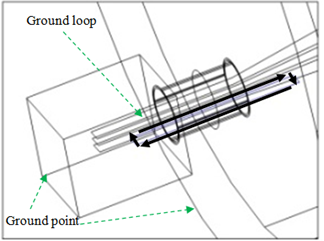
The cable and inverter loops, ground loop and the ground points of the 3DFE model
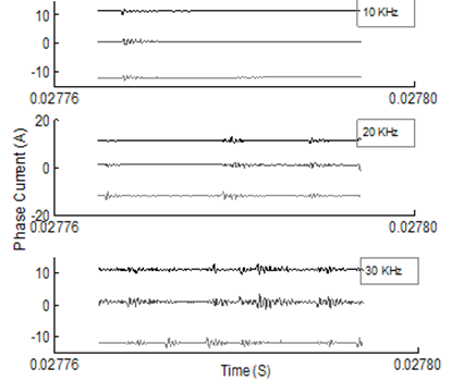
Simulated 3-phase currents at 10 kHz, 20 kHz, and 30 kHz
Simulated CM ground currents at 10 kHz, 20 kHz, and 30 kHz
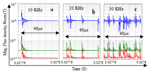
Magnetic flux density over time at three different positions and frequencies. Top, middle, and down waveforms respectively are measured at 0.05 (m), 0.15 (m), and 0.25 (m).
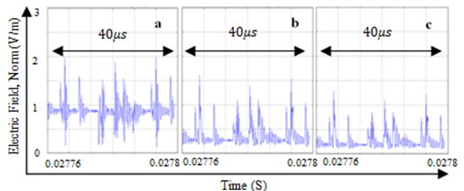
Electric field over time at three different positions for a switching frequency of 30 kHz
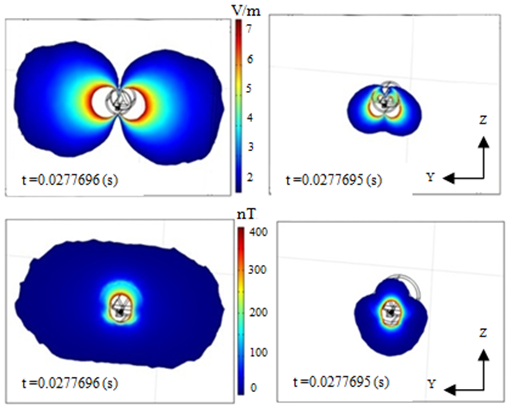
The electric field (top) and magnetic flux density (bottom) before (right) and during switching (left)
The 3DFE model for an electric drive system consisting of a IGBT drive, cable, and PM machine was presented. The model is able to analyze the different effects that the switching frequencies may have on the radiated EMI fields. It is shown how this model can provide us with information about the different radiated field patterns at specific time instances before, during, and after switching and can do so for a variety of different frequencies. The model can also show how the radiated fields behave over a specified time range or as a function of position in order to view the fields relative to different parts of the electric motor drive system at these various frequencies. The ability to analyze these radiated fields at any position or instant of time and for various frequencies can prove to be extremely useful in development and design stages of the electric motor drive. Many scenarios can be tested and mitigation techniques can be investigated to improve EMC compliance without having to repeatedly build and test a physical model.


